Liquid Cooling System Cleanliness Testing
The particles, ions and pH drift you cannot see inside a cold plate eventually surface as rising pressure drop, corrosion perforation and throttled nodes. This guide puts pH, conductivity, turbidity and particle counting where each belongs, across component cleaning, system flushing and day-two operation.
Values from GB/T 48023-2026 Annex A Table A.1 and Annex B flushing requirements, plus the cleanliness clauses of T/CAEE 098-2026. Operating pH must also stay within ±1 of the incoming baseline. Acceptance is governed by the standard text and the project technical agreement.
The short version
Cold-plate cleanliness testing comes down to four measurements: particle counting establishes the size distribution and cleanliness class, pH and conductivity flag ion load and corrosion risk, and turbidity shows total suspended solids. Each is judged at a different stage, and none substitutes for another.
- 01The four parameters answer four different questions: pH and conductivity cover dissolved ions and acid-base balance, turbidity covers total suspended solids, particle counting covers size bands. None can replace another.
- 02Criteria are stage-specific: component delivery, system flushing, incoming coolant and operating coolant are four different frames. Mixing them is the most common reason a cleanliness report gets rejected.
- 03Online monitoring is about trend, not a single reading. Pair supply and return points to answer whether the system is getting dirtier or the filter is doing its job.
Who it is for: design, integration, commissioning and O&M teams on cold-plate liquid cooling projects; manufacturers of CDUs, cold plates, manifolds, hoses and quick disconnects; quality engineers who sign off cleanliness reports and incoming inspections.
Where contamination comes from: particles, ions and suspended solids
Contamination is not simply a matter of "dirty, so flush it". There are three independent failure paths: particle blockage, ionic corrosion, and deposition of suspended solids and biofilm. Collapsing them into one vague "water quality" number is how sites end up with a turbidity reading that looks fine while the cold plate is clogging.
Particles: size and channel geometry decide the outcome
GB/T 48023-2026 sets two filtration tiers: secondary-side filters should be no coarser than 50 µm, primary-side no coarser than 300 µm, and filters should be serviceable while the system is running. T/CAEE 103-2026 goes further for cold-plate manifolds with countable limits: after internal flushing, particles above 100 µm must not exceed 10 per litre, and particles above 50 µm must not exceed 100 per litre. Both point at the same threshold: above 50 µm you are already in the range that needs control.
Bar lengths are an order-of-magnitude guide, not a linear scale. µm(c) denotes the equivalent particle size under the ISO 4406 calibration convention.
A 50 µm filter removes most particles above 50 µm; actual penetration still depends on efficiency, bypass and element condition. ISO 4406 counts concentration bands above 4, 6 and 14 µm(c). The first is a system design and protection setting, the second an acceptance criterion for components and fluid. They are not interchangeable, and a filter rating cannot be used to back-calculate a cleanliness pass.
Ions: conductivity and pH are a pair, not alternatives
Conductivity reflects total dissolved ions in the coolant; pH reflects acid-base balance. Table A.1 of GB/T 48023-2026 specifies incoming secondary coolant pH 8.0–10.0 for copper cold plates or 8.0–9.0 for aluminium; operating pH within ±1 of the incoming baseline and inside 7.0–10.0 (copper) or 7.0–9.0 (aluminium). For conductivity the standard gives a reported value, to be agreed between supplier and buyer.
That is why "the national standard caps conductivity at some number" is a common misreading. The enforceable limit has to be written into the technical agreement, and the report should state "limit per agreement" rather than a blanket "meets the national standard". Flushing has its own hard figures: conductivity no higher than 10 µS/cm at 25 °C, copper and iron each no higher than 0.5 mg/L.
Low pH costs you metal corrosion and a degraded passive film; high pH costs you inhibitor effectiveness, faster scaling and aged seals. Both appear first in conductivity and in dissolved copper and iron, so read these three as a single trend.
Suspended solids and microbes: turbidity measures quantity, not form
Turbidity is an optical quantity, the scattering and absorption of light by suspended particles, and it is not the same observable as a particle count. The standard sets incoming secondary coolant turbidity at ≤5 NTU and operating at ≤20 NTU, with flushing water ≤5 NTU. The same table carries an indicator that is easy to skip: total colony count, ≤100 CFU/mL incoming and ≤1000 CFU/mL operating. Once biofilm forms inside a cold plate channel it raises both pressure drop and turbidity, and cleaning it costs far more than monitoring it.
Secondary coolant (ethylene glycol or propylene glycol aqueous solution): incoming turbidity ≤5 NTU, operating ≤20 NTU. Conductivity is to be agreed between supplier and buyer. After system flushing the water should meet: conductivity ≤10 µS/cm at 25 °C, pH 5–7.5, turbidity ≤5 NTU, copper ≤0.5 mg/L, iron ≤0.5 mg/L.
GB/T 48023-2026, Data center cold-plate liquid cooling system technical specification, Annex A Table A.1 and Annex B flushing requirements (summary; acceptance per the standard text)
How the four parameters divide the work
Site disputes are rarely about instrument accuracy; they are usually about using the wrong parameter to answer the question. Put all four in one table, define each boundary, then talk about selection.
Covers acid-base balance and inhibitor effectiveness. In operation the drift from the incoming baseline matters more than the absolute value.
Covers total ion content. The standard only asks for a reported value by agreement, so range selection is a more useful exercise than hunting for a limit.
Covers total suspended solids with no size resolution. It raises an alarm, but cannot carry a cleanliness classification on its own.
Covers size distribution and cleanliness code; the primary criterion for component acceptance, filter evaluation and failure tracing.
| Parameter | What it tells you | What it cannot see | Key criterion and source | Suggested point | Instrument |
|---|---|---|---|---|---|
| pH | Acid-base balance; whether the inhibitor stays in its effective window | Particles, total ions, microbes | Incoming 8.0–10.0 (copper) / 8.0–9.0 (aluminium); operating within ±1 of the incoming baseline and 7.0–10.0 / 7.0–9.0 (GB/T 48023-2026 Table A.1) | CDU secondary supply and return | BS-PHS276 |
| Conductivity | Total dissolved ions; leading indicator of corrosion and leaching | Suspended particles, size distribution, pH | Operating: reported value by agreement; flushing water ≤10 µS/cm at 25 °C (GB/T 48023-2026) | CDU secondary supply and return; make-up tank | BS-EC350 |
| Turbidity | Total suspended solids; degree of optical attenuation | Size bands, ion concentration, particle composition | Incoming ≤5 NTU, operating ≤20 NTU (GB/T 48023-2026 Table A.1); flushing water ≤5 NTU | CDU return preferred, supply for reference | BS-TURB113 |
| Particles | Particle count per size band and cleanliness code | Ions, acid-base, microbes, particle composition | Delivery ≥ISO 4406 16/14/11 (T/CAEE 098-2026); manifolds per litre (T/CAEE 103-2026); filtration 50 / 300 µm (GB/T 48023-2026) | Side-stream sampling; portable spot checks; cleaner loop | BT8500 / BTP8300 |
"Incoming / operating" values are the secondary coolant frame of GB/T 48023-2026 Annex A Table A.1, covering ethylene glycol or propylene glycol aqueous solutions and other formulated fluids. Formulations differ by project, so check the standard text and the agreement before applying them.
Turbidity is a total. The same 1 NTU can come from a mass of sub-micron particles or from a handful of 100 µm particles; the latter are far more dangerous to a microchannel cold plate, yet may read lower. GB/T 48023-2026 asks CDUs to monitor pH, conductivity and turbidity; it does not mandate an online particle counter. For microchannel cold plates and high-density clusters, add an online liquid particle counter for classification and filter evaluation.
Five stages of liquid cooling cleanliness testing
Cleanliness cannot be secured by one final inspection. Put measurement at five positions, each with its own criteria and instruments, and the data forms a traceable chain.
Component cleaning at the factory
- Object
- Cold plates, manifolds, CDUs, corrugated hoses, quick disconnects
- Criteria
- Delivery cleanliness no lower than ISO 4406 16/14/11 (T/CAEE 098-2026); manifolds >100 µm ≤10/L and >50 µm ≤100/L (T/CAEE 103-2026); cleaning water pH 6–8, conductivity ≤10 µS/cm (YD/T 6358-2025)
- Method
- Put a particle counter on a side stream of the cleaner loop and judge the endpoint from the count-decay curve. Integrate pH and conductivity at the same point to see whether the bath's ion load has already saturated.
- Instruments
- BT8500 (online) or BTP8300 (spot checks) + BS-PHS276 + BS-EC350
- Watch
- Cleaning time does not replace a counting endpoint. The report must state method, sampling and criterion; "meets 16/14/11" without the decision chain cannot be re-verified.
Incoming material and pre-installation
- Object
- Pre-fabricated piping, manifolds, CDUs, site-delivered components
- Criteria
- Internal particulate cleanliness before installation ≤50 µm (T/DZJN 524-2026); secondary CDU filter porosity ≤50 µm; initial internal cleanliness ≤50 µm secondary, ≤300 µm primary (T/CIEP 0228-2026)
- Method
- Spot-check critical parts with a portable counter, and check the supplier's report for method, sampling location and the source of the criterion. A report missing one layer is treated as unverifiable data.
- Instruments
- BTP8300 portable liquid particle counter
- Watch
- Transport, damaged packaging and on-site cutting all reintroduce particles. Keep pre-installation records in a separate file from factory reports.
System flushing acceptance
- Criteria
- Circulate deionised water for no less than 24 h; after flushing pH 5–7.5, conductivity ≤10 µS/cm at 25 °C, turbidity ≤5 NTU, copper ≤0.5 mg/L, iron ≤0.5 mg/L (GB/T 48023-2026 Annex B)
- Method
- Sample and count at fixed intervals and take "no further reduction across consecutive counts" as the endpoint. 24 h is a minimum duration, not a pass certificate; stopping when the clock runs out mistakes a process requirement for an acceptance conclusion.
- Instruments
- Portable particle counter + online pH / conductivity / turbidity
- Watch
- Sample in turbulent sections, away from dead legs and low-point drains. If counts plateau while turbidity stays high, check for bubbles and optical window fouling first.
Fill and operating monitoring
- Criteria
- Incoming pH 8.0–10.0 / 8.0–9.0 and turbidity ≤5 NTU; operating pH within ±1 of baseline and 7.0–10.0 / 7.0–9.0, turbidity ≤20 NTU; conductivity per technical agreement (GB/T 48023-2026 Table A.1)
- Method
- Pair pH, conductivity and turbidity on CDU supply and return; run the particle counter on a side stream. Set two alarm tiers: a warning near the incoming baseline and an alarm at the operating limit, leaving a response window between them.
- Instruments
- BS-PHS276 / BS-EC350 / BS-TURB113 / BT8500
- Watch
- The standard says the CDU "should" monitor these three, which makes it a recommended configuration. Whether to add a particle counter depends on channel geometry and project risk, and belongs in the O&M plan.
Diagnosis and root-cause tracing
- Particle spike
- Check filter differential pressure, pump seals and heat exchanger erosion first, then make-up water carryover; a spike after installation or maintenance is usually construction debris.
- pH drift
- A one-way fall points to inhibitor depletion or microbial activity; a one-way rise to make-up alkalinity and scaling tendency. Sample and retest once drift exceeds ±0.5.
- Conductivity up, turbidity flat
- Ion leaching or make-up water carryover. Check material compatibility and make-up quality before flushing anything.
- Turbidity up, counts flat
- Rule out bubbles, optical window fouling and sediment in the sampling line before concluding that suspended solids really increased.
Start with particles (is it blocking?), then pH and dissolved copper/iron (is it corroding?), then conductivity (where is the ion load heading?), and finally turbidity as a cross-check. Reverse the order and the turbidity total will lead you away from the early size and corrosion signals.
How to cite the 15 liquid cooling standards
In this system, national standards govern the system and the fluid, industry standards govern planning and test methods, and association standards govern component delivery and specialised methods. Mixing the layers is the most common reason a cleanliness report gets rejected: the data is right, but the basis is filed at the wrong level.
| Level | Standard | Title | How this page uses it | Depth |
|---|---|---|---|---|
| National | GB/T 48204-2026 | Information technology - Liquid cooling components for servers and storage equipment | Technical baseline for server and storage liquid cooling components; used for component selection and material / interface benchmarking | Scope |
| National | GB/T 48097-2026 | General specification for cold-plate liquid cooling cabinets in data centers | Cabinet-level structure, interface and O&M requirements; the higher-level basis for cabinet delivery and site acceptance | Scope |
| National | GB/T 48023-2026 | Data center cold-plate liquid cooling system technical specification | Primary source of criteria here: secondary coolant pH / conductivity / turbidity, flushing water limits, filter rating, CDU monitoring points | Clause |
| Industry | YD/T 7463-2026 | Planning requirements for cold-plate liquid cooling computing centers | Capacity, layout and supporting requirements at the planning stage; determines where measurement points and sampling access can sit | Scope |
| Industry | YD/T 7105-2026 | Test methods for cold-plate liquid cooling data centers | How acceptance tests are executed; the field procedure for water quality and particle testing | Clause |
| Industry | YD/T 6358-2025 | Technical requirements for cold-plate liquid cooling data centers | Cleaning water quality for component delivery: pH 6–8, conductivity ≤10 µS/cm, plus pre- and post-cleaning drift limits | Clause |
| Association | T/DZJN 524-2026 | Design requirements for liquid cooling data centers | Internal particulate cleanliness ≤50 µm before installation; secondary CDU filter porosity ≤50 µm | Clause |
| Association | T/CIEP 0227-2026 | Design specification for fully liquid-cooled data center systems | Design frame for fully liquid-cooled systems; used at concept stage to define the monitoring scope | Scope |
| Association | T/CAEE 099-2026 | Piping and components for data center liquid cooling systems - cold plate type | Dedicated requirements for cold-plate piping and components; a technical supplement for component acceptance | Scope |
| Association | T/CAEE 098-2026 | General technical requirements for piping and components in data center liquid cooling systems | Delivery cleanliness criterion: no lower than ISO 4406 16/14/11; a normative annex gives the flush - sample - count - look-up method | Clause |
| Association | T/CAEE 103-2026 | Performance and test specification for manifolds in data center liquid cooling systems | Particle-per-litre limits inside manifolds, used alongside the ISO 4406 code rather than instead of it | Clause |
| Association | T/GDSS 021-2026 | Technical specification for stainless steel piping in liquid cooling - data centers | Material, cleanliness and installation requirements for stainless steel piping; drives the starting contamination level before flushing | Scope |
| Association | T/CAEE 112-2026 | Technical specification for stainless steel corrugated hoses in server liquid cooling systems | Requirements for corrugated hoses; cleanliness control in quick-disconnect and flexible sections | Scope |
| Association | T/CIEP 0263-2026 | Technical specification for data center liquid cooling systems | System-level technical requirements; complements the system criteria used on this page | Scope |
| Association | T/CIEP 0228-2026 | Installation and manufacturing guide for CDU piping and auxiliary control components in data centers | Initial internal cleanliness ≤50 µm on the secondary side, ≤300 µm on the primary side | Clause |
"Scope" means the standard is cited only for its field of application, to define the object and stage, with no figures extracted. "Clause" means specific figures are cited and traceable to a clause. GB/T 48023-2026 was published on 30 July 2026 and takes effect on 1 February 2027; YD/T 7105-2026 took effect on 1 November 2026. Status of the remaining standards should be checked on the National Standards Information Public Service Platform and the national association standards platform.
| Layer | Question it answers | Where it goes in the report |
|---|---|---|
| Method | How was it sampled, flushed and counted, and what was the blank? | Test method field: extraction or flushing method, cleaning fluid, filter pore size, sample volume, blank value and rounding rules |
| Limit | What is the pass line, and who says so? | Basis field: national standard clause, association standard class, or customer technical agreement number - never mixed in one line |
| Verdict | In which state, and for which batch, is the call being made? | Conclusion field: component delivery, post-flushing and operating period get their own columns and their own verdicts |
When standards conflict, which one wins
Two sets of limits in one report is normal: a general association standard gives an ISO 4406 class, a dedicated one gives particles per litre; a national standard gives an operating range, a customer agreement gives a tighter internal value. Resolve it in this order: contract or technical agreement first; without one, the dedicated standard before the general one, and the stricter of equals; where the standard is silent (secondary conductivity, for example), fall back to the agreement and label it "reported value". Whichever way it resolves, put one source in the verdict field and the other in the comparison column.
Quoting the flushing water limits of GB/T 48023-2026 (pH 5–7.5, conductivity ≤10 µS/cm, turbidity ≤5 NTU) as the delivery cleanliness criterion for a single cold plate measures a different object altogether. The reverse error - writing the 16/14/11 class of T/CAEE 098-2026 as an operating water quality requirement - equally exceeds its scope. Component versus system, delivery versus operation: separate columns.
One point is routinely overlooked: GB/T 48023-2026 is a recommended national standard (GB/T) and is not mandatory in itself, but once a tender, purchase contract or technical agreement cites it, it binds that project. Before 1 February 2027 you can use it for technical benchmarking and pre-acceptance, but you should not publicly claim "certified to this national standard". Clause-by-clause notes are in our GB/T 48023-2026 clause review.
Measurement points and integration: placement beats specification
A sensor in the wrong place makes precision irrelevant. Three rules govern the secondary side: representative sampling, serviceable in operation, and no disturbance to the main loop.
| Point | What goes there | Location and sampling | Watch out |
|---|---|---|---|
| Supply main | pH, conductivity, turbidity | Turbulent straight run downstream of the CDU outlet; insertion depth per pipe size and datasheet | Avoid the pump discharge pulsation zone and the first elbow; pH and conductivity must be temperature-compensated |
| Return main | pH, conductivity, turbidity | Upstream of the CDU inlet, paired with the supply point | Only the supply-return difference shows load-section contamination and filter effect; a single point shows status only |
| Side-stream sampling | Online particle counter | Tapped from the supply main, through a degassing unit and back-pressure valve, returning to the return main | No pipe cut and no sudden diameter change; keep sample flow stable so bubbles are not counted as particles |
| Cleaner loop | Particle counter, pH, conductivity | Side stream of the cleaning tank circulation line, in parallel with the cleaning process | Confirm wetted-material compatibility with the cleaning agent; judge the endpoint from the count-decay curve |
| Make-up / reservoir | Conductivity, pH | Downstream of the make-up inlet, below tank level, avoiding stagnant zones | Make-up water is a common cause of conductivity steps; log readings before and after every top-up |
All four instrument families offer RS485 Modbus RTU or 4–20 mA output and can tie into the CDU PLC or the data center BMS. Four rules for integration:
- Unified timestamps. Water quality and particle data must share one clock, otherwise a correlation such as "pH was drifting while counts spiked" cannot be established.
- Tiered alarms. A warning near the incoming baseline, an alarm at the operating limit, and a response window between them. With a single threshold the site can only ignore it or shut down.
- Trend retention. Keep raw curves for at least one full O&M cycle for filter life assessment and post-incident review; daily summaries alone will not reconstruct an event.
- Serviceable side stream. The particle sampling branch must be removable, cleanable and calibratable while the system runs, otherwise every service visit stops the whole loop.
Sampling points must sit in a turbulent section, not in the stagnant zone downstream of elbows, valves or tees, and not directly at a low-point drain, where deposited particles are swept out and inflate the reading. Particle sampling lines should avoid sudden diameter changes and horizontal runs that trap air; add a degasser and maintain back pressure where needed.
Instrument selection: range, installation and sampling
Four parameters, four instrument families. Select in this order: range from the fluid and the criterion, then installation and sampling from the piping, and finally communications and maintenance.
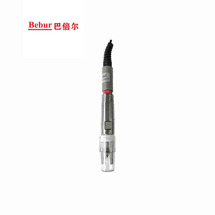
BS-PHS276 pH sensor for liquid cooling
Low-conductivity fluidsDesigned for the low ion concentration of deionised water and ethylene or propylene glycol solutions. A low-impedance sensing glass stays stable at low conductivity, PT1000 automatic temperature compensation removes the effect of temperature swings, and internal signal isolation copes with the electrical noise of a data hall.
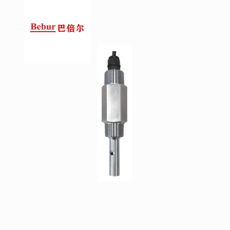
BS-EC350 conductivity sensor for liquid cooling
Four rangesAnti-polarisation and signal isolation reject external interference, and the sensor is compatible with propylene glycol, ethylene glycol and deionised water. Ranges A, B, C and D span deionised water through concentrated glycol solutions; choose by the actual fluid and operating window rather than defaulting to the widest range.
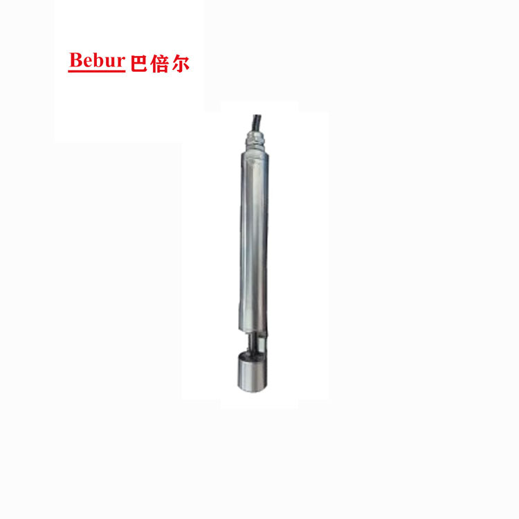
BS-TURB113 turbidity sensor for liquid cooling
Through-beam opticsThe emitter sends light at a fixed wavelength and the receiver measures transmission through the coolant; suspended solids scatter and absorb it, and the attenuation maps to turbidity. A through-beam layout with a sapphire window is unaffected by reflections from stainless piping, and the built-in wiper brush limits bubbles and fouling for long-term online use.

Online and portable liquid particle counting
Light extinction · 8 channelsLight-extinction counting: a particle passing the cell blocks a laser, pulse amplitude maps to size and pulse count to number. BT8500 covers long-term side-stream monitoring and production cleaning stations, BT8200 suits multi-point line integration, and the portable BTP8300 handles incoming inspection and flushing acceptance.
Three selection rules
- Size the conductivity range to the fluid. Deionised water uses 0–20 µS/cm (range A); PG25 / EG25 service usually falls in 0–200 or 0–1000 (B / C); wide or concentrated duty uses D. An oversized range wastes resolution where the readings matter.
- Size the turbidity range to the criterion. A 0–10 NTU range decides the ≤5 NTU incoming limit; 0–100 NTU covers the ≤20 NTU operating limit and the high turbidity of flushing. A model that switches ranges online suits a shared flushing-and-operation instrument.
- Set particle channels by target size. ISO 4406 needs the >4, >6 and >14 µm(c) bands; for the 50 / 100 µm component limits, confirm the lower range limit, channel setup and calibration can resolve the target size - never let "widest range" stand in for "effective resolution".
These parameters were checked against Bebur product pages on 2026-11-10. Configurations and options can change between batches; confirm against the current datasheet and order agreement before ordering.
Field notes and five common myths
The same instruments, installed differently, vary by an order of magnitude in data credibility. The six points below are where sites most often go wrong, and what is worth confirming first when a method goes live.
Bubbles are the first error source in particle counting
Light extinction cannot tell a bubble from a solid particle. Flushing, pump suction and the moments after a top-up entrain microbubbles and can double or triple the reading. Side-stream sampling needs a degasser and back pressure, and the tap should sit away from pump inlets and downstream of make-up points.
Sampling representativeness decides whether the data is usable
Sample in a turbulent straight run, not in the stagnant zone downstream of elbows, valves or tees, and not straight from a low-point drain. Avoid sudden diameter changes and horizontal runs that trap air, and hold flow at the datasheet design value.
An oversized range makes the low end unreadable
Four conductivity ranges are not a case of bigger being better. On deionised water the 0–20 µS/cm range is what resolves the small changes at the end of flushing; using 0–2000 µS/cm everywhere throws away two decades of effective resolution.
Temperature compensation is not optional
pH and conductivity both move with temperature, and the standard limits themselves are referenced to 25 °C. Use PT1000 automatic compensation for pH and convert conductivity to 25 °C; uncompensated readings cannot be compared across different supply temperatures.
Set the maintenance interval from the fouling rate
The wiper brush limits turbidity fouling, but the optical window still needs periodic inspection. Calibrate the pH probe on a schedule and keep it in 3 mol/L or saturated KCl when idle. Maintenance and calibration records must be filed together, or the data is not traceable.
Criteria cannot be borrowed across stages
Flushing water, component delivery, incoming coolant and operating coolant are four sets of criteria. Put one stage's standard number on another stage's conclusion and the report is rejected even when the data is right. Separate columns, separate standards, separate states: that is the minimum.
Five common myths
- "Turbidity is normal, so cleanliness passes." Turbidity is a total and cannot resolve size. ISO 4406 counts the 4, 6 and 14 µm(c) bands, and microchannel risk comes mainly from large particles; a low turbidity reading does not prove they are absent.
- "The national standard sets a conductivity ceiling." GB/T 48023-2026 gives secondary conductivity as a reported value to be agreed between the parties. The enforceable limit comes from the technical agreement, and the report should state "limit per agreement".
- "A 50 µm filter means no particle exceeds 50 µm." A filter rating describes the element's retention class, not the maximum particle size in the system. Bypass, element failure and start-stop surges all let particles larger than 50 µm reach the cold plate.
- "Twenty-four hours of flushing is a pass." 24 h is the minimum duration the standard gives; pH, conductivity, turbidity and copper/iron still have to be judged afterwards. Treating the clock as the conclusion mistakes a process requirement for an acceptance criterion.
- "With online instruments, lab sampling is unnecessary." Online instruments carry trend and alarms; arbitration and disputes still require sampling and retesting by the standard method. They are complementary, not substitutes.
One integration that is already in service
Component cleaning is where all four parameters are easiest to use together: you need to know when the count has reached its endpoint, and whether the bath's ion load has already saturated.
The method is simple: integrate an online particle counter, a pH sensor and a conductivity sensor on a side stream of the cleaning machine's circulation line, without cutting the main pipe or changing the existing flow, and watch the count-decay curve alongside the bath's pH and conductivity. The endpoint is decided from data, not from an operator's stopwatch.
According to Bebur's published technical material, this integration is in service in the liquid cooling component cleaning line at Boyd's Dongguan plant, monitoring solid particles, ionic impurities and pH online and feeding the cleaning result back in real time. The same material notes an improvement in the defect rate after integration.
The published material describes the integration and the measurement points; it does not promise any outcome for any project. Actual results depend on the cleaning process, filtration setup, sampling representativeness and operating discipline, and any case figure should be quoted together with its test conditions and statistical basis.
Frequently asked questions
These are the questions that come up most often in selection discussions and site commissioning. Where a clause exists, the answer cites it rather than saying "it depends".
Does a cold-plate liquid cooling system need an online particle counter?
GB/T 48023-2026 asks the CDU to monitor secondary coolant pH, conductivity and turbidity on a “should” basis; it does not mandate an online particle counter. A turbidity meter alone meets that basic recommendation, but turbidity is a total and cannot resolve the 4 / 6 / 14 µm bands. For microchannel cold plates, add an online particle counter for cleanliness classification and filter evaluation.
Is GB/T 48023-2026 mandatory, and when does it take effect?
It is a recommended national standard (GB/T), published on 30 July 2026 and effective from 1 February 2027. A recommended standard is not mandatory in itself, but once a tender, purchase contract or technical agreement cites it, it binds that project. Until then you can use the text for benchmarking and pre-acceptance, but do not claim “certified to this national standard” before 1 February 2027.
What is the acceptance limit for secondary-side conductivity?
Table A.1 gives conductivity as a reported value to be agreed between supplier and buyer; there is no single national ceiling. Write the limit into the technical agreement and label the report “limit per agreement” rather than “meets the national standard”. Flushing has a separate, explicit requirement: no more than 10 µS/cm at 25 °C.
How are the incoming and operating pH criteria applied?
Per Table A.1: incoming pH 8.0–10.0 for copper cold plates or 8.0–9.0 for aluminium; operating pH within ±1 of the incoming baseline and inside 7.0–10.0 (copper) or 7.0–9.0 (aluminium). Operating acceptance needs both conditions at once: drift within 1 of the baseline and an absolute value inside the window. Checking only the absolute value misses slow drift.
Can a turbidity meter replace a particle counter for cleanliness decisions?
No. Turbidity is optical attenuation of the total suspended solids, while ISO 4406 requires counts in three bands - above 4, above 6 and above 14 µm(c) - reported as a three-digit code. The same 1 NTU can come from many small particles or a few large ones, and the risk to a microchannel cold plate differs sharply. They are complementary: turbidity for trend and alarms, particle counting for classification and acceptance.
If flushing water passes, is the component's cleanliness acceptable?
No. The flushing water limits in GB/T 48023-2026 (pH 5–7.5, conductivity ≤10 µS/cm, turbidity ≤5 NTU, copper and iron ≤0.5 mg/L) describe the fluid state after system flushing. Component delivery cleanliness should cite the ISO 4406 16/14/11 class of T/CAEE 098-2026, and manifolds the particles-per-litre limits of T/CAEE 103-2026. Different objects, different criteria, and never the same verdict field.
Why does liquid particle counting need a degassing unit?
Light-extinction counting relies on particles blocking a laser, and bubbles behave optically much like solids, so they are counted and inflate the result. Flushing, pump suction and post-top-up conditions entrain microbubbles. Degassing, back pressure and avoiding sampling at pump inlets are the prerequisites for usable data.
Should water-quality sensors go on the supply or return line?
Ideally both, as a pair. The supply point shows the coolant entering the cold plates, the return point shows what changed across the load, and only the difference answers whether the system is getting dirtier or the filter is working. A single point shows status but cannot separate sources or evaluate filtration. If only one point is possible, use the return main and note the limitation in the report.
Criteria first, then points, then instruments
Cleanliness programmes are often run in reverse: buy the instrument, find somewhere to mount it, then open the standard. The right order is to fix the basis and the stage first, then decide points and sampling; the instrument only executes. Get the criterion wrong and greater accuracy makes the report less credible, not more.
If you are configuring water quality and particle monitoring for a cold-plate project, check the range against the fluid and the criterion, confirm sampling and installation conditions, then look at communications and maintenance. Full specifications and measuring principles for the four instruments are in the links below.
Related reading
- BS-TURB113 Liquid-Cooled Turbidity Sensor
- BS-EC350 Liquid-Cooled Conductivity Sensor
- BS-PHS276 Liquid-Cooled pH Sensor
- Liquid Particle Counter for Water, Oil and Coolant Monitoring
- Streaming Current Detector for Coagulation Control
- Peracetic Acid Analyzer for Water PAA Monitoring
- Water Hardness Analyzer BC300
- Hydrogen Peroxide Analyzer for Water H2O2 Monitoring